|
|
|
|
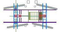
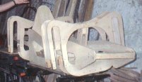
Some Development Images |
|
|
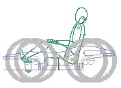
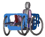
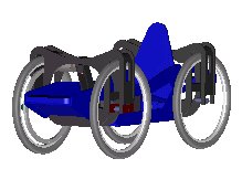
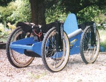
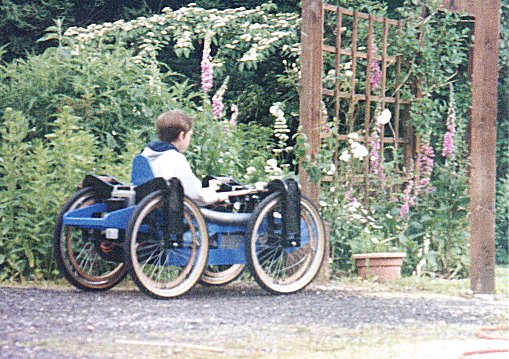
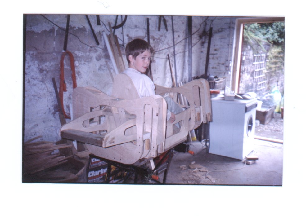
Buggy No. 2 is based on the same electrical drive components as Buggy No.1. It is also a 4-wheel drive, 4-wheel steered off-roader but, as you can see, this time a single seater. Its more compact design makes it more easily transported, and reduces the likelihood of arguments as to who drives, but importantly its smaller size and change in structural material results in it being a lighter vehicle than its predecessor. This weight reduction reduces the drive forces required and so results in reduced mechanical loading on the hub motors and ultimately in reduced electrical loading on them, the controller and batteries. Lower current draw, cooler running motors, generally lower electrical losses and increased battery life are the result. As before simplicity of
manufacture and minimization of cost were design aims. The structure is
mainly of ply and planed soft wood with a screwed and glued
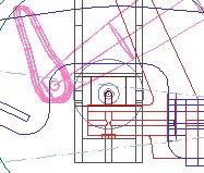
construction, a joining method which has proved remarka The ISKRA electric motors are permanently connected through the transmission to the wheels and in conjunction with the 4QD controller provide both acceleration and braking. The mechanical drives provide a single stage speed reduction of about 21:1 without expensive gearing. Each consists of an inverted toothed belt driving a toothed drive rim connected to the wheel. They involve an interesting use of plywood, lengths of toothed belt and super-glue and have proved the trickiest part of the vehicle to design. This slightly more sophisticated drive system is more sensitive to wheel damage than its predecessor as it requires proper alignment of the meshing belts to be maintained; this can be lost when a wheel is slightly buckled after impacts. T The vehicle is more stable than Buggy No.1 with its lower center of gravity and wheels more or less fixed at the structure corners and has proved difficult for the kids to roll. The gearing ratio has been reduced compared to its predecessor, partly to reduce the load on the motors. In combination with lighter weight this has improved on the already impressive acceleration of Buggy No.1 to such an extent that the acceleration control adjustments of the 4QD controller have been brought into play to “soften” its performance. Top speed is also impressive at about 20kmph. All in all its a vehicle that requires some practice to drive well and has encouraged the kids to look ahead when driving and anticipate conditions and situations before they are on top of them. Problems with the design
include heavier steering due to the increased number of loaded pivot
points. This could be addressed by incorporating thrust bearings into
the pin joints to reduce friction. Struct Developments would be mainly limited to making the above improvements. However other improvements would concern the steering which is currently by a tiller/handle bar arrangement directly connected to the front wheel supports. This isn't, apparently, as “cool” as it could be and a more sophisticated steering wheel arrangement would be of interest, although more expensive to build. The tiller carries a twist grip type accelerator with a separate forward/reverse switch. The 4QD series controller allows a joystick type speed control and removing the reverse switch in favour of a single, zero-centered twist control would be of interest also. © This site is copyrighted. If you'd like more information or have any comments please feel free to contact me at
|
|

 bly strong. This time there are no welded
metal structures. Critical load bearing elements such as pins and wheel
attachments are in steel as are the core elements of the transmissions
but other than that timber is the main material. Mountain bike wheels
are retained and the 4 motor drive avoids the requirement for extended
mechanical power transmission components and produces wheel speed
differential for cornering. Articulation of the front wheel support
about the fore-aft axis maintains four-wheel ground contact without
complex suspension components and steering is achieved through rotation
of both the front and rear wheel supports about their vertical axes;
again no complex steering parts.
bly strong. This time there are no welded
metal structures. Critical load bearing elements such as pins and wheel
attachments are in steel as are the core elements of the transmissions
but other than that timber is the main material. Mountain bike wheels
are retained and the 4 motor drive avoids the requirement for extended
mechanical power transmission components and produces wheel speed
differential for cornering. Articulation of the front wheel support
about the fore-aft axis maintains four-wheel ground contact without
complex suspension components and steering is achieved through rotation
of both the front and rear wheel supports about their vertical axes;
again no complex steering parts. he more
compact vehicle packaging has made the drives less easy to access than
before although they are less obtrusive visually. The
he more
compact vehicle packaging has made the drives less easy to access than
before although they are less obtrusive visually. The 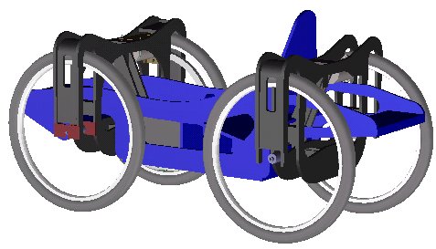 ural
weaknesses of the timber housings for the heavily loaded pins is also
apparent giving problems associated with pin hole elongation. This
could be solved by adding local reinforcements in the form of steel
bosses at the pin holes. And finally some structural weaknesses are
evident as a result of frontal impacts with garage walls, trees etc.!
This could be solved by not running into garage walls, trees etc. but
this can be difficult to achieve... given the drivers!
ural
weaknesses of the timber housings for the heavily loaded pins is also
apparent giving problems associated with pin hole elongation. This
could be solved by adding local reinforcements in the form of steel
bosses at the pin holes. And finally some structural weaknesses are
evident as a result of frontal impacts with garage walls, trees etc.!
This could be solved by not running into garage walls, trees etc. but
this can be difficult to achieve... given the drivers!