|
 The
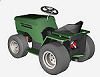
mini garden tractor is one of my earlier designs and I now
have a newer 1300W Yard tractor design available - click on
the small image on the right to go to its web page. The
mini garden tractor is one of my earlier designs and I now
have a newer 1300W Yard tractor design available - click on
the small image on the right to go to its web page.
The new design is a more robust vehicle with a
bigger drawbar pull.
The Earlier Design
This early mini
tractor was a different beast from its predecessors.
Designed less for fun and more for practical use around the garden. It
is fun to use however although its lack of protective structure around
the wheels means it can't be run into walls etc without damaging
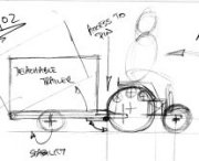
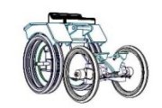
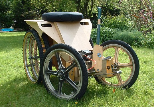
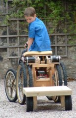
consequence: it needs to be driven with more care. It has a standard
tractor form with large rear wheels for traction and smaller front
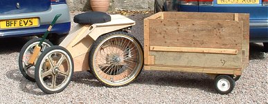
wheels for steering. A draw bar is built in low and close to the rear
axle and a simple and effective trailer provided for practical use.
Overall design aims were to produce a compact vehicle with useful tractive capability for garden use. Ease of access for the user and
good manoeuvrability were also aims.
 The vehicle width and length have been constrained to achieve
compactness necessary for storage and manoeuvrability. Structure does
not protrude beyond the wheel envelopes so allowing the tractor to be
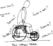
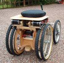
manoeuvred in tight spaces. The seating position is above and forward
of the rear axle to contribute to the COG position which gives
stability and required weight over axle for effective traction. Clear
access for the driver to and from the seating position also results.
Steering is by hand tiller and speed control by foot pedal. The two
40Ah 12v
batteries are set low between the front and rear axles easily
accessible for charging or removal. The drive components are set above
and between the rear wheels. The tow bar position is set to ensure ease
of trailer engagement/disengagement and effective transfer of haulage
forces into the structure. The vehicle width and length have been constrained to achieve
compactness necessary for storage and manoeuvrability. Structure does
not protrude beyond the wheel envelopes so allowing the tractor to be
manoeuvred in tight spaces. The seating position is above and forward
of the rear axle to contribute to the COG position which gives
stability and required weight over axle for effective traction. Clear
access for the driver to and from the seating position also results.
Steering is by hand tiller and speed control by foot pedal. The two
40Ah 12v
batteries are set low between the front and rear axles easily
accessible for charging or removal. The drive components are set above
and between the rear wheels. The tow bar position is set to ensure ease
of trailer engagement/disengagement and effective transfer of haulage
forces into the structure.
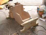
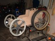
 The structure is of ply and planed soft wood with a screwed and glued
construction much like Buggy No.2. There are no welded structures. In
this vehicle all wheels are cantilevered from their support structures
and through hardened
steel axles have been used all round to carry the
increased bending moments. The axles are supported by deep groove ball
bearings housed in the vehicle's wooden structure. The front wheels are
carried on a wooden beam axle pinned to the main vehicle structure to
provide articulation necessary to keep the front wheels in ground
contact on uneven ground.
The structure is of ply and planed soft wood with a screwed and glued
construction much like Buggy No.2. There are no welded structures. In
this vehicle all wheels are cantilevered from their support structures
and through hardened
steel axles have been used all round to carry the
increased bending moments. The axles are supported by deep groove ball
bearings housed in the vehicle's wooden structure. The front wheels are
carried on a wooden beam axle pinned to the main vehicle structure to
provide articulation necessary to keep the front wheels in ground
contact on uneven ground.
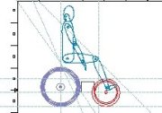
The steering geometry is modified ackerman to reduce tyre
scrub on cornering. The front wheel support structures have been the
source of some redesign work; some elements made from wood would
probably better be made in
steel to carry the considerable local forces
that exist on turning and impact. A hand tiller provides the steering
actuation and is effective in giving adequate sensitivity of control
and is an improvement over original plans for the foot steering system
shown in some of the images.
 The rear drive wheels are doubled-up mountain bike wheels. This
enhances load bearing capacity and produces a stiffer wheel assembly
better capable of resisting lateral loading. It also improves traction
over that provided by single bike wheels. Lateral stiffness of the
wheels is significant because of the drive train design and its need
for reasonable running alignment of the drive rims attached to the
wheels. The front wheels are also bike wheels but smaller, in this case
plastic moulded BMX wheels. All wheels have had their existing ball
races stripped and replaced with static connections to the rotating
axles. The rear drive wheels are doubled-up mountain bike wheels. This
enhances load bearing capacity and produces a stiffer wheel assembly
better capable of resisting lateral loading. It also improves traction
over that provided by single bike wheels. Lateral stiffness of the
wheels is significant because of the drive train design and its need
for reasonable running alignment of the drive rims attached to the
wheels. The front wheels are also bike wheels but smaller, in this case
plastic moulded BMX wheels. All wheels have had their existing ball
races stripped and replaced with static connections to the rotating
axles.
The unladen tractor weighs about 80kgf and the trailer
26kgf. With driver and 100kgf load the all up mass is about 280kg.
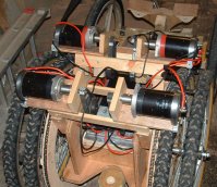 The core drive components; the motors,
controller and
batteries have
been inherited from the previous vehicles. Each rear wheel assembly is
driven by two permanently engaged DC PM
motors through 2 stage speed
reductions of about 36:1. Expensive or difficult to obtain reduction
gearing has been avoided by using a combination of synchronous belt and
sprocket on
chain drives. The large reduction results in sufficient
drive torque to haul the loaded trailer (and other loads) but has
reduced the top speed to about 12 km/h. This is fine for garden use.
Adhesive bonding of drive components onto shafts has again been
employed to ease manufacture. These bonds have sustained full torque
loading through the drive train including full stall conditions for the
motors. The bonding may give problems in the future when parts need to
be changed though! The core drive components; the motors,
controller and
batteries have
been inherited from the previous vehicles. Each rear wheel assembly is
driven by two permanently engaged DC PM
motors through 2 stage speed
reductions of about 36:1. Expensive or difficult to obtain reduction
gearing has been avoided by using a combination of synchronous belt and
sprocket on
chain drives. The large reduction results in sufficient
drive torque to haul the loaded trailer (and other loads) but has
reduced the top speed to about 12 km/h. This is fine for garden use.
Adhesive bonding of drive components onto shafts has again been
employed to ease manufacture. These bonds have sustained full torque
loading through the drive train including full stall conditions for the
motors. The bonding may give problems in the future when parts need to
be changed though!
The
4QD
controller gives sensitive speed control in both forward and reverse.
 No mechanical brakes have been fitted, mainly because our garden is
pretty level with only local steep gradients and the motors and
controller effectively decelerate and stop the vehicle. A parking brake
might be considered to stop vehicle creep when loaded and stationary on
an incline. No mechanical brakes have been fitted, mainly because our garden is
pretty level with only local steep gradients and the motors and
controller effectively decelerate and stop the vehicle. A parking brake
might be considered to stop vehicle creep when loaded and stationary on
an incline.
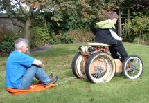
The tractor hauls well, the
limit so far is that of traction; the wheels usually spin before the
motors stall. Manoeuvrability is good, although the younger drivers
have discovered that reversing a tractor and trailer isn't quite as
easy as it looks.
Battery life isn't much of an issue as it's use in
the garden is for mainly intermittent duties. I haven't been able to
gauge this properly yet and the batteries are on their 3rd
vehicle and aren't what they once were.
The principal noise from the
tractor is the characteristic “buzz” from the chain drive
rims... it's still much quieter than an IC powered vehicle though.
 Problems have mainly been those related to stressed joints in timber ie
pin and
bearing housings. These tend to open out slightly under the
action of the compressive contact stresses from the steel pins or
bearings inducing some unwanted movement in the wheels or steering.
This has been resolved by inserting packing but should be addressed by
reinforcement of the housing holes. An initial front wheel support
structure configuration failed due to over stressing on some wooden
parts and was redesigned. Problems have mainly been those related to stressed joints in timber ie
pin and
bearing housings. These tend to open out slightly under the
action of the compressive contact stresses from the steel pins or
bearings inducing some unwanted movement in the wheels or steering.
This has been resolved by inserting packing but should be addressed by
reinforcement of the housing holes. An initial front wheel support
structure configuration failed due to over stressing on some wooden
parts and was redesigned.
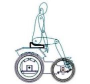
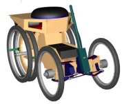
We didn't get around to
painting the tractor, if we had it probably would have ended up looking
like the CAD rendering shown just above.
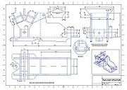
Engineering drawings of the tractor are available as a free downloadable
sheets.....have a look at the
tractor plans page.
Here are three short .AVI video clips showing the tractor running
shortly after building - there's no cover or proper seat on yet!
Top
©
This site is
copyrighted.
If you'd like more information or have any
comments please feel free to contact me at
|