Electrical and Control System Details
 I've
written the Wi-Fi Bot Driver software application which handles the comms
over the wireless network. This allows the joystick control signals to be communicated
from the fixed PC to the mobile robot and also allows a live
read-back of the condition of the motor speed
controllers on the bot. This is a key part of the control system. It is made up of two programs - Sender and Receiver,
which run on the fixed and mobile PC's respectively. The Sender program
reads the state of the joystick on the fixed PC and transmits this using
UDP protocols to the receiving PC. If required the Sending program can
instead output the control signals directly to a serial port on the fixed PC.
This is useful for wired debugging of the bot or for onward transmission
by
wireless telemetry links.
I've
written the Wi-Fi Bot Driver software application which handles the comms
over the wireless network. This allows the joystick control signals to be communicated
from the fixed PC to the mobile robot and also allows a live
read-back of the condition of the motor speed
controllers on the bot. This is a key part of the control system. It is made up of two programs - Sender and Receiver,
which run on the fixed and mobile PC's respectively. The Sender program
reads the state of the joystick on the fixed PC and transmits this using
UDP protocols to the receiving PC. If required the Sending program can
instead output the control signals directly to a serial port on the fixed PC.
This is useful for wired debugging of the bot or for onward transmission
by
wireless telemetry links.
The Receiver program running on the board notebook/laptop converts
commands received over the network into a local serial output which is
read by a PICAXE micro controller based processor unit (SPU) to provide
the local control over the machine. The Receiver program exports the
state of three axes and 8 button buttons on the sending joystick and
could be used to provide a serial feed to any microcontroller based
applications that can read serial data.
The bot driver software uses standard network IP addresses and port
numbers to identify the participating PC's. The data flow can be
interrupted at either PC to disable the robot.
The bot Signal Processor Unit reads the serial data from the notebook PC
(or direct from the fixed PC) and mixes the joystick forward/reverse and left/right axis data to
determine speed and direction required of each drive motor, it then
sends the speed and direction instructions to the motor speed
controllers on the robot. It also instructs RC style servos which
provide pan and tilt for the onboard webcam  (so you can see where you
are going if the robot is in a different room or off exploring in the
back garden).
(so you can see where you
are going if the robot is in a different room or off exploring in the
back garden).
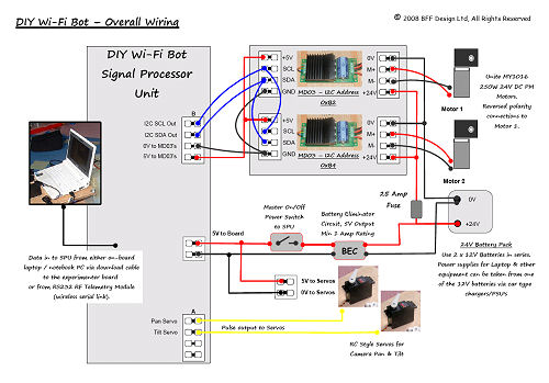
The
overall system wiring for the robot is shown above. The SPU is built on
the picaxe experimenter board and uses two 28X1 picaxe chips. The master
chip handles the serial comms with the laptop and drives two Devantech
MD03
motor controllers on an I2C bus. It also passes the state of the
designated pan and tilt joystick buttons on the the 2nd or slave 28X1
chip which issues servo pulse commands to drive two camera position
servos.
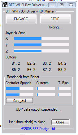
Monitoring the Robot's Condition
The communications provided by the robot driver
software is two-way. The on-board SPU reports the motor speed controller
speed settings, current flow and temperature back to either the Notebook
PC carried on the bot (for onward transmission to the master PC) or
directly to the master PC. This feedback data is displayed live on the
sender program window. This gives the driver live feedback of the
current draw and temperatures of the speed controllers - it makes for
interesting watching.
 The
Bot Driver Software is also able to dump this feedback data to a text
file where the data can be inspected more closely. For example the trace
below shows the current flow in the MD03 speed controllers during simple
straight line travel and then during full on-the-spot skid-steer
rotations. It is generally known that skid steering consumes much more
power than more conventional steering approaches but it's interesting to
see the effect directly.
The
Bot Driver Software is also able to dump this feedback data to a text
file where the data can be inspected more closely. For example the trace
below shows the current flow in the MD03 speed controllers during simple
straight line travel and then during full on-the-spot skid-steer
rotations. It is generally known that skid steering consumes much more
power than more conventional steering approaches but it's interesting to
see the effect directly.
|
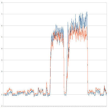
Motor Controller Currents during
Skid-Steer Turns |
The trace is a bit noisy but small up/down steps can be
seen over the initial part of the trace matching the initial simple
forward and reverse straight line motion of the bot. The current draw in
each controller looks like it is approximately 0.3/0.4 Amps - ie it
requires little effort to travel on the flat in a straight line. However
the jump in the current draw during the skid-steer turns can be seen
clearly, The current draw rises to roughly 5 to 6 Amps with some
peaks higher as the speed of the turns gets faster. I haven't included a
temperature trace but it shows the controller temperatures climbing
during the period of higher current draw. The MD03's are rated for 20
Amps and the 250W motors for 14 Amps so the currents are still well
within capacity but it is still interesting to see the scale of the
higher power demand as the wheels are dragged and spun during the turns.
Back to Page 1......
On to Page 3 for Machine Vision