 Gears provide one
of the most compact ways of building a speed reduction
transmission between two shafts and it is this
compactness
that makes them attractive for our kind of designs. All
my geared designs use simple parallel shafts and what
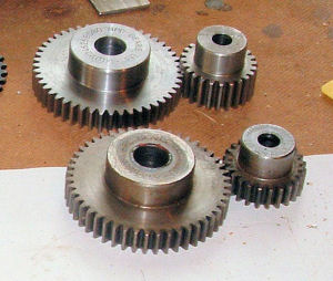
are called straight spur gears. I use steel spur gears
because they are readily available in (almost) standard
sizes and are the least expensive, although their cost
can vary quite a bit depending upon where you get them.
The "standard" bit is the gear tooth form & size and the
number of teeth on the gear, for example several
manufacturers can supply, say, a 1 module, 24 tooth spur
gear (the "module", or "diametral pitch" for imperial
gears, is the specification of the tooth size, the
number of teeth is - well, the number of teeth on the
circumference) however the face width of the gear, the
boss diameter, the bore size etc will all probably vary
between makers, as may the steel used and its strength
and surface hardness and the degree of precision to
which the gear is cut. Fortunately my designs don't
push these steel gears to the limits and fairly
bog-standard materials and accuracies are fine so I
have found that even the least expensive gears will run
and last. The issue is obtaining the right basic spec
(module & no. of teeth) and checking that the particular
gear dimensions fit the space available.
 Most
of the time I use 1.5 module gears, I have found that
these offer a good compromise between availability, size
range available and tolerance to the inevitable slight
inaccuracies of positioning that arise with home built
projects. Not coincidentally they are available from a
number of sources.
There are several points to bear in mind when trying to
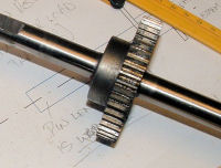
use gears. They have to be torque-fixed to the shaft
supporting them and throughout our designs we have used
adhesive bonding methods to do this - see the gearbox
plans. This has been a very successful and convenient
means of attachment; other than drilling out the gear
bore to the required diameter there is no other special
machining required on either the gear or its shaft, the
resulting torque joint is strong enough for my designs
and it can also be dismantled by heating the joint.
 Downsides
for the builder are the relative accuracy with which the
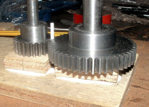
shafts must be positioned for the gears to mesh properly
and, off course, the cost of the gears. Accurate shaft
positioning is something we deal with in our gearbox
designs so have a look at the gear box plans to see how
its done. If you are not convinced that gluing a gear to
a steel shaft will be strong enough - try it! Even if
you use domestic superglue to do the job (not what we
recommend) removing the bonded gear from the shaft by
brute force is very difficult - so long as the bond area
is adequate (used "bossed" gears) and the bond gap and
adhesive distribution is good (get the hole/shaft
clearances right) the joint strength can be
considerable.
I will no doubt need to use bevel gears at some stage
to connect shafts at right angles but I don't think
there will be a need for helical teeth on either the
spurs or these bevels. The increased power transmission
capacity offered by these forms doesn't warrant the
extra cost for my types of designs.