In my experience one of the hardest things to get right when building
an electric (or other) buggy is getting the mechanical drive from the
motors to the drive wheels right. Over the years I've tried all sorts of novel mechanical power transmission methods from friction drives (Tandem Buggy) and inverted toothed belt drives (Sporty) to sprocket on chain-rim drives (Mini Tractor). Some of these work better than others, some are more reliable than
others. Perhaps not surprisingly however, if you can make them,
the drives that work best are those most commonly used in the
engineering industries - involute gear, chain & sprocket or belt & pulley
drives.
For the DIY-er or home-builder there's a big
problem here however - usually gears or sprockets are keyed or splined
to shafts, shafts are stepped in diameter to fit into bearings, metal
bearing housings are bored-out to accept the bearings and the housings
are precision machined in the walls of steel or aluminium gearbox
casings. How do you do any of this if you
don't have access to the range of specialised metal cutting machine tools usually found in an engineering works?
The answer is to
avoid doing it - through some intelligent design of the gearbox. The
gearboxes we have developed for use in our most recent designs use
carefully selected combinations of common engineering components,
adhesive bonding methods and particular build constructions
and procedures that allow them to be built with much less
sophisticated tooling.
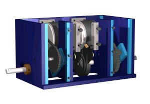
There are three
boxes shown on the site - one single motor unit and two double motor units, one of which
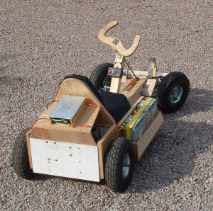
has built in band-brakes (as used in the Go Kart
). Some of their design features are:
- Self contained - multiple drive components don't
need to be separately attached to the buggy main frame or chassis.
Drive wheels are attached directly to the output shafts.

- Timber cases - easier to make and easy to secure to.
- A combination of roller chain and gear
stages to obtain overall speed reduction ratios from about 10:1 to 27:1
from the motor output shaft and wheel axle speeds. A range of different
final stage gears can be used at the build stage to set the reduction
ratio needed for a particular application.
- 1st stage (motor) chain drive which is more
forgiving of slight inaccuracies in the motor positioning than a geared
1st stage - this allows the motor fixing methods to be simple.
- Adhesive bonding of gears/sprockets to
shafts - no need for splines, keys or stepped shafts. The only
machining required is to drill-out gear/sprocket bores to match shaft
sizes, no stepping of shaft diameters.
- Inexpensive needle roller bearings on all shafts.
- Steel shafts for strength with bench ground end flats for torque attachments..
- Build procedures to allow accurate positioning
of bearing housings in the casing to set correct shaft centre distances
and alignments.
 With the electric scooter motors we use in the gearboxes a range
of output shaft speeds are obtained between about 150 rpm and 370 rpm
depending on which 2nd stage gears are used. The motors have rated
power outputs of 250W giving a total of 500W output for the double
motor unit. The braked unit has built-in scooter band brakes which
brake directly the final axle - this provides mechanical braking
which is independent of the electrical drive. Note however that
band-brakes are more effective in one direction than the other so the
braked unit has particular "forward" and "reverse" directions.
By using gear and
roller chain stages and roller bearings throughout, the boxes are
efficient and loose little drive energy in transmission.
Importantly for buggy use they are both reversible (can be driven in
reverse) and back-driveable (can be driven from the output shaft). This
later characteristic allows the use of "4 quadrant" motor
controllers to provide some dynamic, re-generative braking for the
application. Another practical application of this is to allow the
vehicle to be towed relatively easily when the drive motors are
isolated from their controller.
Follow the links below for .pdf files of the gearbox assemblies.
One
final note (and a wee admission of failure), try though we might I could not figure
out how to fix the final stage gear to a suitably sized final
drive shaft without drilling a hole in the gear bigger than most common
bench drills could handle. The final shaft is approx 16 mm in diameter
to give bending strength required to support the wheel loads. 16 mm in
steel is too big for a small bench drill. So this remains the one bit
most competent DIY-ers, who don't have or have access to a small lathe,
will find problems with. The solution is straightforward however - get
the gear manufacturer to do it for you - many will happily, for a small
additional charge, modify the bores on their gears to suit customers.
See the assembly sheets
here for the
gearbox with brakes!